The Raspberry Pi 4 provides a wide range of possibilities when it comes to the design of embedded operating systems. Throughout this class, we have used the RPi for a variety of applications, including the development and implementation of scripts to control the system's processes, the installation of different Linux kernels, and GUI configuration on the PiTFT display screen. Furthermore, the RPi has been used as a microcontroller with its general-purpose input/output pins (GPIO), to control motors, sensors and other types of actuators.
For this final project, we wanted to create a physical gaming system with embedded controls and a GUI on the PiTFT screen. We considered several alternatives, but we finally landed on an old-school pinball machine, which we called the "PiNBall". Old pinball machines are a childhood classic for most students our age, and the team considered that it was the perfect choice for our project since it implements various elements studied throughout the class.
Our design consists of a physical build, which is made out of laser-cut wooden pieces held together by screws, hardware elements connected to the GPIO pins on the RPi, and a Python script that controls the hardware and the graphical user interface.
The hardware elements used for the pinball's gameplay are: two 3-D printed flippers, glued to two DC motors; three bumpers made out of rubber bands, with internal aluminium contacts that increase the player's score when they are hit; two arcade-style buttons to control the motors; and a Pi Camera mounted on top of the board, which keeps track of the balls position using computer vision and activates the flippers in a self-playing mode.
The Python code was designed to create a touch GUI on the PiTFT display, with buttons to select a game mode, display your score during a game, and activate or deactivate the motors. The system presents three main game modes: (1) a classic one-player mode, which is played for 30 seconds to obtain a high score; (2) a two-player mode, in which two players compete to obtain the highest score; (3) a self-playing mode, which uses the Pi Camera and computer vision to activate the flippers.
Objective
The purpose of the project is to create an old-school pinball machine, mixing hardware and software elements in an embedded operating system. The physical build is made out of laser-cut wooden pieces, and the hardware includes two arcade-style buttons to activate two 3-D printed flippers moved by DC motors, a motor driver that takes in a PWM signal and forward and backward voltages, aluminium contacts inside of three rubber band bumpers to keep track of the player's score, and a Pi Camera mounted on top of the board that uses computer vision in a self-playing mode. The code was written in Python, which controls all of the hardware and the GUI on the PiTFT display screen.
Design & Testing
Design
Hardware
The hardware implementation for this project can be divided into a physical build made out of wood, and the electronics that include various sensors and actuators.
Physical build
The wooden pieces used for the pinball's encasing were first designed manually, taking into account the angle of inclination of the board (Fig. 2). Adjustments were made to the "playground's" (wooden board where the ball rolls through) angle to make it less steep, and a reduction in size was done in order for all the pieces to fit in the laser cutter. Additional holes here drilled in the side pieces to implement the two arcade-style buttons, and on the playground's surface to pass wiring down to a breadboard where all the electronics were connected (bumper wires, and motors).
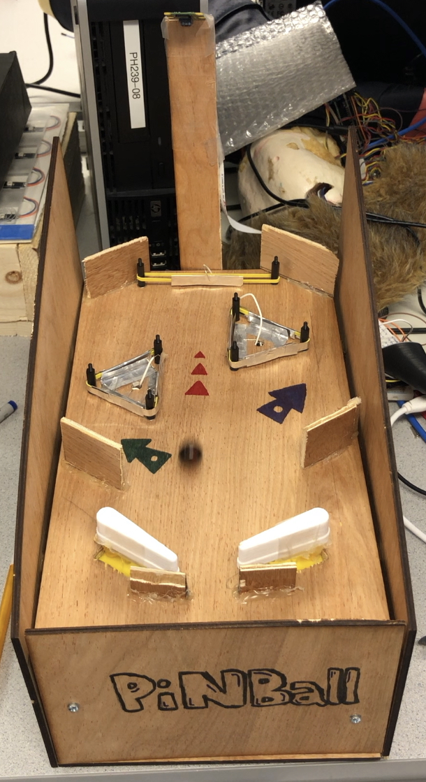
FIGURE 2: Encasing of the PiNBall System
.
The pieces were held together using steel corner braces, screwed on both sides to the wooden pieces. This is a simple method for joining wood, and it is strong and reliable.
Electronics
We used several electronic parts for the overall functioning of the pinball machine. As previously mentioned, one of the main parts is the ball-launching system. The team initially thought of using servo motors for this, since they can achieve precise angular motion, perfect for our application.
However, after ordering and implementing them into our system, we realized that the servo's movements were too slow to launch a marble upwards on the playground's slope. After a bit of testing, we decided to use DC motors. Although its movements are not precise, the team used wooden stops glued to the board to force the range of the flippers' motion. This solution worked perfectly, and the motion was fast enough to launch the ball at an acceptable speed. The DC motors, powered by 6.8 V obtained from the lab's power supply, were glued underneath the board, which had hole openings to mount the flippers. A drawback from using these motors is that we need three GPIO pins for each motor: two pins for forward and backward rotation respectively; and one pin to send a PWM signal to the motor driver. The motor driver we used was the SparkFun Dual TB6612FNG used in class.
The flippers (Fig. 3 & 4) were 3-D printed and mounted on the DC motors using hot glue. The STL file was edited to scale the piece down to an appropriate size.
FIGURE 3: Flipper Top View
FIGURE 4: Flipper Bottom View
The bumpers were a challenging part of the physical build. We needed something simple and bouncy, to launch the ball on the opposite direction when hit. Our choice for this was a triangular shaped rubber band, fastened around three vertical cylinder poles (Fig. 5 & 6). The rubber band bends inwards after being hit by the ball, so we placed aluminium contacts both in on the rubber bands, and around the inside of the bumper. This way, if the ball bumps into the rubber band, it will connect the two contacts, and the player's score will be increased. Two triangular bumpers were built, and a third simpler bumper was built near the end of the board, using only two cylinder poles.
FIGURE 5: All three bumpers
FIGURE 6: Individual bumper
Two arcade-style buttons were placed on the sides of the system for a more authentic pinball experience. Each one is connected to a GPIO pin on the RPi, and they were implemented with the Python code to activate the motorized flippers (Fig. 7 & 8).
FIGURE 7: Right button
FIGURE 8: Left button
Finally, the Pi Camera was mounted on a wooden piece, overseeing the playground board. The range of vision of the camera was adjusted in the code, and its main objective was to detect when the ball was near the bumpers to activate them automatically in the self-playing mode.
FIGURE 9: Mounted Pi-Camera
Software
The code that controls the logic of our project has been created using Python. It is found in two separate files: project.py and camera_trial.py. The first one contains most of the logic, including control of all Raspberry Pi actuators and sensors, as well as the GUI. The later file contains the computer vision algorithm used to detect when the ball is close to the flippers, for self-playing mode.
The playing modes that have been implemented are Arcade, with both one and two-player modes, and self-playing mode. When entering arcade mode, a timer starts, and the player must earn as much points as possible while the timer is counting down. When the game is over, there is a final screen where the scores are displayed. The buttons on the side that control the flippers only work when the game is being played.
Threading has been necessary to implement two parts of the application:
When a button is pressed, it triggers a function that moves the flipper. This function makes a call to time.sleep(...) to keep the motor moving during a certain amount of time. If this code is executed on the main thread, every other functionality of the project, including the GUI or the camera, would stop working while the flipper is moving. This was solved, by launching the move_flipper(...) function in a separate thread.
Similarly, the camera algorithm was also launched in a separate thread in order for it to be able to work simultaneously with other components. When the camera is instantiated a callback is passed as an argument, which is called when the algorithm detects that movements has occurred near the flippers.
Some classes have been developed to make the control of the project easier. These are:
Playing Environment: when playing, this class contains a set of variables regarding which game we are playing on, and also controls the time left. It also handles the player scores.
Button Tracker: this class keeps track of all GUI buttons. It has information regarding in which screen each button is displayed, its coordinates, and which screen does the button lead to. In the main loop of the program, when a touch event has been detected, the ButtonTracker instance is notified by sending the coordinates of the event, and it is in charge of changing the appropriate variables (e.g. change screen and initiate a game).
The camera algorithm uses a background subtractor method obtained from the Internet, which detects all moving parts of the screen. Then this parts are filtered to find one that is located with a rectangular area above the flipper. If there is one, the flipper will be activated.
Testing
A lot of hours of testing and debugging went into this project. Once we manually designed the system's encasing, we had to make some changes to scale down the dimensions to be appropriate for the laser-cutting machine. Several different methods were tested to join the wooden pieces together, and we finally decided to drill holes and connect them using corner braces.
A big part of the testing involved the motors, and their involvement in our system. As mentioned, we needed a fast motion, capable of launching a small marble across the playing board. The servo motors we initially ordered were tested to be too slow for our application, and we decided to use DC motors. After connecting them to the board, we tested different ranges for forward and backward motion, and we glued wooden stops to force the angle to be what we wanted.
The bumpers were also a big part of the testing process, as we initially did not know how to make this part work. After exploring different options, we decided to use tensed rubber bands in triangular shapes. Holes had to be drilled on the playing board to pass wires down to the RPi, and aluminum contacts were added inside of the bumpers to count the points. This was a frustrating process, since the aluminium bends easily and does not stay completely rigid. The bumper contacts worked as intended, and the points were counted towards the player's score. However, we would have liked the bumpers to be more sensitive and responsive, since they would sometimes ignore some of the bumps.
Finally, the Pi Camera that uses computer vision for the self-playing mode required a lot of testing and adjustment. Once we placed it on a wooden piece facing the playing board, adjustments in the code were necessary for its optimal performance. First, the range of the camera's vision was adjusted to only fit the board, to avoid capturing shapes moving around the board (objects or people). Second, the code was designed to only consider black-colored objects, and with specific size dimensions similar to the marble. This way, the camera only cared about our marble, and activated the flippers accordingly.
Results & Conclusion
After completing the project, we have successfully achieved a viable product of what was intended. Flippers work correctly and the ball is sent with enough strength to reach the upper part of the game table. Also, it is possible to obtain points by pressing the bumpers, and the camera algorithm is able to play with the ball autonomously for an extensive period of time.
Although some improvements could be made (see Future Work), we are satisfied with the results that we have obtained within the time frame in which the project was developed.
Overall, the team learned valuable insights from this project. We designed and built an encasing for the system, we connected all the necessary electronic components through the Raspberry Pi, we implemented a touch GUI on the PiTFT display screen, and we developed the Python code to control the system. We implemented various elements learned throughout the class and during the labs, and we created a functioning, fun, embedded operating system from scratch.
Other info
Future work
There are some improvements that could be made to our project. Some of these are:
Improving bumper sensors: it could be useful to make bumper sensor more sensitive, because sometimes the ball would hit the bumper but no points are added to the player.
Improving the camera algorithm: there are some improvements that could be made, for example, detecting the direction of the ball and triggering only one flipper instead of both. Also, making the algorithm calculate better when the ball will hit the bumper and react in an optimal way.
Add more elements, for example, speakers and LEDs rings to create a better gaming experience.
Budget
The only component that has not been provided by the University is the Arcade-style buttons which were used to activate the flippers. The total cost was $12.95.
Work Distribution
Daniel García Garrigó
Connect wood pieces using screws and joints
Drill holes to connect the arcade-style buttons
Adding motors and flippers using hot glue
Building the rubber band bumpers and adding aluminium contacts